
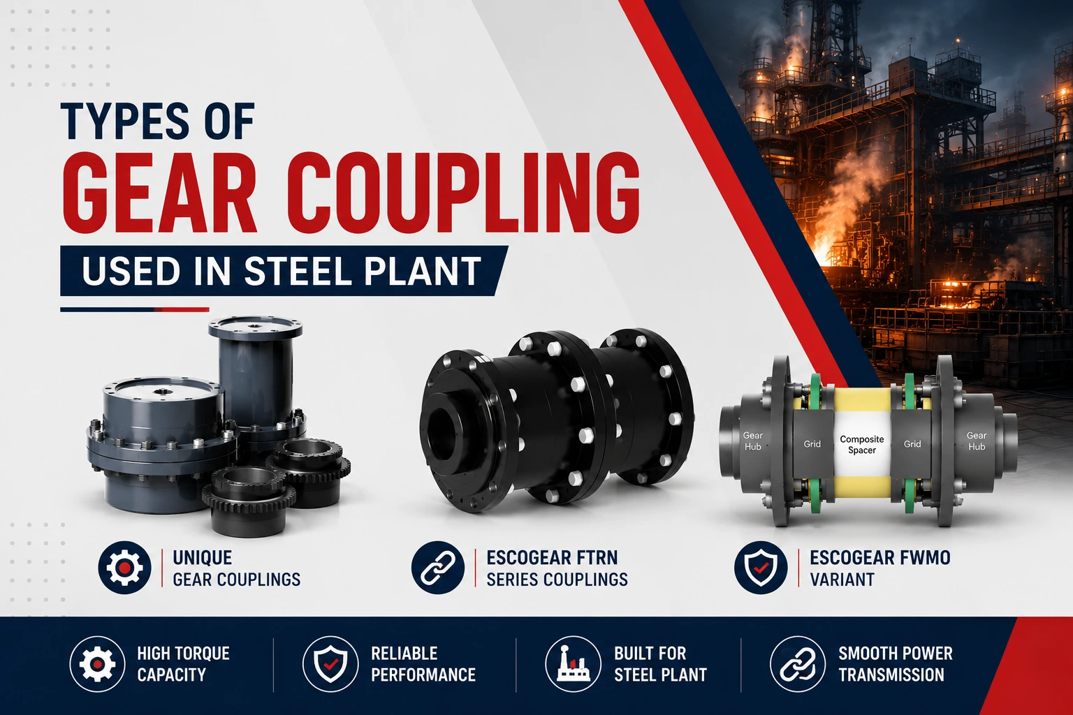
Steel plants run on power transmission that never gets a day off. Rolling mills, continuous casters, blast furnace blowers, cranes, and conveyor drives all depend on couplings that can transmit enormous torque while tolerating shaft misalignment, vibration, thermal expansion, and shock loading. Among the many coupling families available, gear coupling technology remains the workhorse of heavy industry because of its compact size, high torque capacity, and ability to handle both angular and parallel misalignment without sacrificing reliability.
This guide breaks down every major type of gear coupling used across steel plant operations, explains where each one fits best, and outlines the selection and maintenance factors that keep production lines running without unplanned downtime.
Why Gear Couplings Are Preferred in Steel Plants
Before getting into the types, it helps to understand why gear couplings dominate steel plant applications rather than other coupling styles:
- High torque density – a gear coupling can transmit far more torque per unit size than most flexible couplings, which matters when space around a mill stand or gearbox is tight.
- Misalignment tolerance – the crowned gear teeth allow angular, parallel, and axial misalignment while continuing to transmit full torque.
- Shock load absorption – steel rolling and casting operations generate sudden load spikes; gear couplings are built to absorb and transmit these without catastrophic failure.
- Long service life – with proper lubrication, gear couplings can run for years in continuous, high-load environments.
- Serviceability – most designs allow disassembly without moving the connected machines, which is critical for minimizing downtime during maintenance windows.
These properties are why gear coupling remains the default choice across rolling mills, continuous casting lines, and material handling systems in integrated steel plants.
Main Types of Gear Coupling Used in Steel Plants
1. Full-Flex (Flexible) Gear Coupling
The full-flex gear coupling consists of two hubs with crowned external gear teeth, each engaged with an internally toothed sleeve. Both ends flex, which allows the coupling to accommodate misalignment at both connection points simultaneously.
Where it’s used in steel plants:
- Motor-to-gearbox connections on rolling mill drives
- Blower and fan drives in blast furnace and sinter plant auxiliaries
- Pump drives in cooling water and hydraulic systems
Why it works here: Full-flex couplings are compact, handle moderate-to-high misalignment, and are easy to maintain because the sleeve can typically be split or slid back without disturbing the connected shafts.
2. Half-Flex (Spacer) Gear Coupling
A half-flex or spacer gear coupling has one flexible (geared) end and one rigid, keyed or flanged end. The rigid end is usually mounted directly to a pump or fan shaft, while the flexible end absorbs misalignment on the driver side.
Where it’s used in steel plants:
- Vertical pump applications in descaling and cooling systems
- Applications where only one shaft is prone to misalignment
- Equipment requiring a fixed spacer distance for maintenance access
Advantage: Reduces cost and complexity where full flexibility at both ends isn’t required, while still simplifying pump or motor removal for servicing.
3. Continuous Sleeve Gear Coupling
This variant uses a single continuous sleeve spanning both hub sets rather than a split or flanged design. It’s a compact, economical option for applications with lower misalignment demands.
Where it’s used in steel plants:
- Auxiliary drive systems such as conveyors and small material handling motors
- Light-to-medium duty fan and pump applications
- Areas where axial space is limited but coupling replacement isn’t frequent
4. Flanged Sleeve Gear Coupling
Flanged sleeve gear couplings use bolted flanges to connect the sleeve halves, making disassembly and reassembly faster and more precise. This design is common where couplings need frequent inspection or removal for maintenance.
Where it’s used in steel plants:
- Main drive trains on rolling mills where scheduled maintenance is frequent
- Continuous casting machine drive assemblies
- Reduction gearbox connections on heavy-duty crane hoists
Advantage: Bolted flanges allow quick access to internal gear teeth for lubrication checks and wear inspection without full coupling removal.
5. Floating Shaft (Spool Piece) Gear Coupling
This design uses an extended spacer or “spool” shaft between two gear coupling assemblies, allowing the coupling to bridge longer distances between connected equipment while still accommodating misalignment at both ends.
Where it’s used in steel plants:
- Long-distance drive shafts between motors and mill stands
- Applications where equipment layout requires significant separation between driver and driven units
- Vertical or offset shaft arrangements common in continuous casting and reheating furnace drives
6. High-Performance (High-Speed) Gear Coupling
Engineered for high rotational speeds and precision balancing, these gear couplings are used where drive systems operate at elevated RPMs and even small imbalance can cause vibration damage.
Where it’s used in steel plants:
- Turbine-driven blower and compressor trains in power and utility sections of the plant
- High-speed auxiliary drives in sinter and coke oven plants
7. Gear Spindle Coupling (Mill Spindle Coupling)
A specialized heavy-duty gear coupling designed specifically for rolling mill applications, the gear spindle coupling connects the mill drive to the working rolls. It’s built to handle extreme torque, shock loading, and frequent roll-change misalignment.
Where it’s used in steel plants:
- Hot strip mills, plate mills, and bar/rod mills
- Roll stand connections requiring frequent disassembly during roll changes
Why it’s critical: This is one of the most demanding coupling applications in the entire plant, since it must survive constant shock loads from the rolling process while allowing rapid roll changeovers.
Comparing Gear Coupling Types at a Glance
| Coupling Type | Misalignment Handling | Best Suited For |
|---|---|---|
| Full-Flex | High (both ends) | Motor-to-gearbox, pumps, fans |
| Half-Flex (Spacer) | Moderate (one end) | Vertical pumps, single-side misalignment |
| Continuous Sleeve | Low-Moderate | Conveyors, light auxiliary drives |
| Flanged Sleeve | Moderate-High | Rolling mill drive trains, cranes |
| Floating Shaft (Spool) | High (long spans) | Long-distance drive connections |
| High-Performance | Low (precision balanced) | High-speed turbine/blower trains |
| Gear Spindle | Very High (shock + misalignment) | Mill stand roll connections |
Selection Criteria for Steel Plant Gear Couplings
Choosing the right gear coupling type isn’t just about torque rating. Steel plant engineers typically evaluate:
- Torque and shock load requirements – rolling and casting operations generate cyclic and shock loads far beyond nameplate motor torque.
- Misalignment expected in service – thermal growth, foundation settling, and installation tolerances all contribute.
- Speed of rotation – higher speeds demand tighter balancing and precision manufacturing.
- Lubrication method – grease-packed vs. continuously lubricated designs affect maintenance intervals.
- Space constraints – shaft spacing and access for maintenance influence whether a spacer or spool design is needed.
- Frequency of maintenance access – flanged and split-sleeve designs speed up inspection and replacement.
For a deeper technical breakdown of coupling design, materials, and lubrication standards, see our full gear coupling resource page.
Applications Across the Steel Plant
Gear couplings aren’t limited to one section of a steel plant — they’re present across nearly every major process area:
- Rolling mills: Gear spindle couplings and flanged sleeve couplings connect drive motors to roll stands, handling continuous shock loading from the rolling process.
- Continuous casting machines: Full-flex and floating shaft couplings connect drive rolls and withdrawal units where alignment shifts with thermal cycling.
- Blast furnace and sinter plant auxiliaries: Full-flex and high-performance couplings drive blowers, fans, and compressors.
- Material handling and cranes: Flanged sleeve and continuous sleeve couplings are used in hoist and travel drive gearboxes.
- Cooling water and descaling systems: Half-flex spacer couplings connect vertical pumps to their drivers.
These use cases reflect just one part of how gear couplings serve heavy industry. To see how coupling requirements differ across other sectors such as cement, power generation, and mining, visit our industries page for sector-specific coupling guidance.
Maintenance Best Practices for Steel Plant Gear Couplings
Even the best-designed gear coupling will fail prematurely without proper upkeep. Common maintenance practices include:
- Scheduled relubrication – gear teeth require proper grease intervals based on speed and operating temperature; steel plant heat exposure often shortens standard intervals.
- Periodic alignment checks – laser alignment during planned outages prevents accelerated tooth wear.
- Wear inspection – checking crowned teeth for pitting, scoring, or excessive backlash during turnarounds.
- Seal replacement – damaged seals allow grease contamination or loss, a leading cause of premature gear coupling failure in dusty steel plant environments.
- Torque and balance verification – especially important for high-speed couplings connected to turbines or blowers.
Conclusion
From full-flex couplings on auxiliary pump drives to heavy-duty gear spindle couplings on rolling mill stands, gear coupling technology is engineered into nearly every rotating drive train in a modern steel plant. Selecting the right type comes down to matching torque, misalignment, speed, and maintenance requirements to the specific application.


