
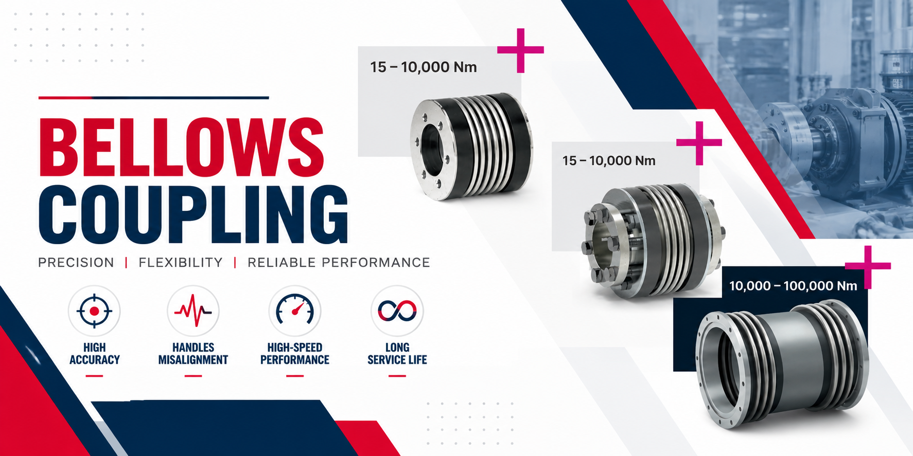
A coupling rarely gets much attention when a machine is running properly. It becomes important when vibration increases, shafts move slightly out of alignment, positioning accuracy drops, or a drive system starts putting unwanted loads on connected equipment.
Bellows couplings are designed for applications where transmitting rotation accurately matters, but the connection between two shafts cannot always remain perfectly rigid.
Their thin metallic bellows section provides flexibility while still transmitting torque from one shaft to another. This combination makes them useful in precision machinery, automation equipment, servo systems, encoders and other applications where low backlash and accurate motion transmission are important.
But a bellows coupling is not automatically the right choice for every drive.
Understanding how it works, where it performs well, its limitations and how to size it correctly is more useful than simply choosing one from a catalogue.
Selecting a bellows coupling is easier when the application details are clear. Torque, operating speed, shaft diameter, expected misalignment, mounting arrangement and working conditions should all be considered before choosing a coupling.
RSV Industries is an Industrial Coupling Distributor supplying coupling solutions for different power transmission and industrial applications. Along with bellows coupling requirements, customers can discuss other coupling options based on their machinery, shaft arrangement and operating conditions.
What Is a Bellows Coupling?
A simple bellows coupling definition is:
A bellows coupling is a flexible shaft coupling that uses a thin, corrugated metallic bellows element between two hubs to transmit rotational torque while accommodating limited shaft misalignment.
The bellows flexes when small angular, axial or parallel displacement occurs between the connected shafts.
Unlike an elastomeric coupling, the flexible section is normally metallic. This gives a flexible metal bellows coupling characteristics that are particularly useful where accurate rotational transmission and torsional stiffness are required.
The terms bellow coupling, bellows coupling, bellow type coupling and bellows shaft coupler are often used when referring to this general coupling design.
Main Parts of a Bellows Coupling
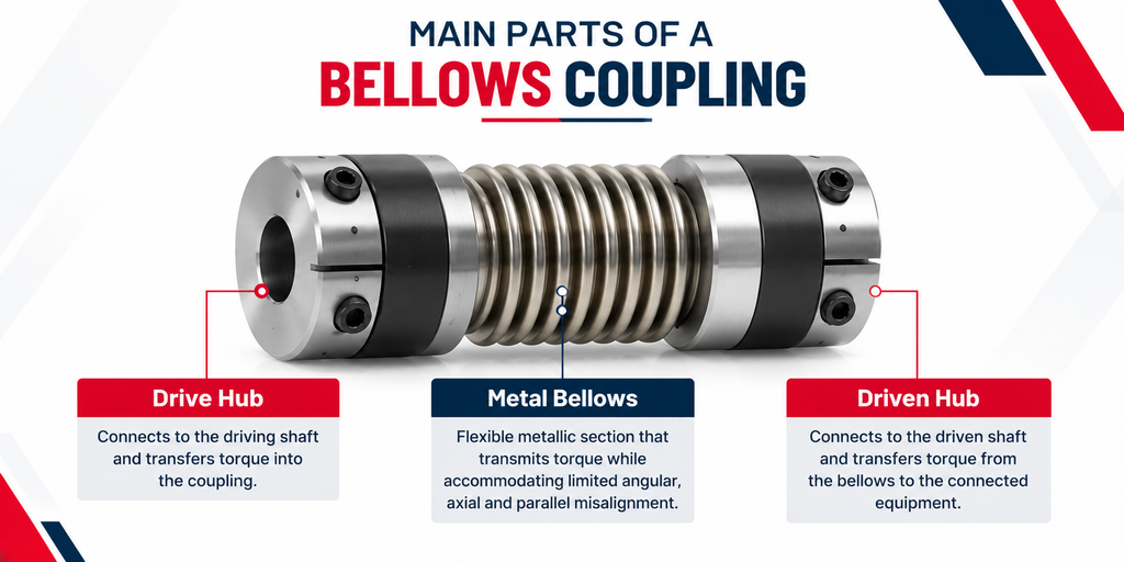
Although designs vary, a typical bellows coupling has three main functional areas:
Drive hub → Metal bellows → Driven hub
The hubs connect the coupling to the shafts.
The metal bellows forms the flexible section between them.
Different products may use clamping hubs, set-screw hubs or other shaft attachment arrangements depending on the application.
How Does a Bellows Coupling Work?
Imagine a servo motor connected directly to a precision positioning mechanism.
The motor rotates, so torque must pass from the motor shaft to the driven shaft. If both shafts were perfectly aligned and remained that way under every operating condition, a completely rigid connection could theoretically transmit the motion.
Real equipment is different.
There may be slight angular error during installation. Temperature can change dimensions. Bearings and machine structures have tolerances. Small axial or parallel movement can occur.
The bellows section flexes to accommodate permitted movement while transmitting rotation between the two hubs.
Because the metallic bellows can provide high torsional stiffness, properly selected designs are particularly useful where the driven side needs to follow the motor movement accurately.
What Happens During Misalignment?
The bellows deforms slightly according to the type of displacement.
With angular misalignment, the shaft centerlines meet at a small angle.
With parallel misalignment, the centerlines remain parallel but are offset.
With axial movement, the distance between the shaft ends changes slightly.
The important word here is slightly.
Bellows couplings have specified misalignment limits. They should not be used to compensate for badly installed or severely misaligned machinery.
Where Are Bellows Couplings Used?
The bellows coupling application range is different from that of many conventional heavy-duty industrial couplings.
Their strengths are particularly valuable in precision motion systems.
Servo Motor Systems
Servo systems require accurate response between the motor and driven component.
A torsionally stiff, low-backlash connection can help maintain precise motion transmission, making bellows couplings suitable for many servo drive arrangements.
CNC and Machine Tools
Machine tools rely on controlled movement and repeatable positioning.
Bellows couplings can be used between motors and components such as ball screws or other positioning mechanisms where motion accuracy is important.
Encoders and Sensors
An encoder needs to follow shaft movement accurately to provide reliable position or speed feedback.
Small flexible bellows couplings can connect the encoder shaft while accommodating permitted installation misalignment.
Robotics and Automation
Automated systems frequently combine servo motors, sensors, positioning equipment and precision mechanisms.
These are environments where compact dimensions, torsional stiffness and low backlash can be important coupling characteristics.
Laboratory and Measurement Equipment
Precision measuring and testing equipment can also use bellows shaft couplers where accurate rotational movement needs to be transmitted between relatively small shafts.
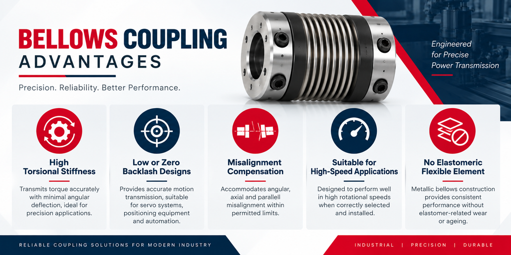
The reason engineers specify bellows couplings becomes clearer when the application requires both flexibility and precision.
High Torsional Stiffness
The metallic construction can provide high resistance to twisting under load.
This helps reduce the difference between input and output rotational movement, which is valuable in positioning systems.
Low or Zero Backlash Designs
Many precision bellows coupling designs are engineered for backlash-free torque transmission.
This is particularly useful in servo, encoder and positioning applications where direction changes occur frequently.
Misalignment Compensation
The bellows can accommodate specified angular, axial and parallel misalignment.
This provides controlled flexibility without relying on an elastomeric insert.
Suitable for High-Speed Applications
Correctly selected bellows couplings can operate at relatively high rotational speeds.
However, maximum RPM should always be checked against the manufacturer’s technical data for the specific size and configuration.
No Elastomeric Flexible Element
The flexible section is metallic.
This can be useful where the operating environment or precision requirements make an elastomeric flexible element less desirable.
Bellows Coupling Disadvantages
A useful selection guide also needs to explain where the product does not fit.
Bellows couplings have limitations.
Limited Misalignment Capacity
The flexible bellows can compensate for misalignment, but only within its specified limits.
Excessive offset or angular error repeatedly flexes the bellows beyond its intended operating range and can shorten service life.
Not Designed for Every Shock Load
Applications with severe impact or shock may require a coupling specifically designed to absorb those loads.
A high-precision bellows coupling and a shock-absorbing elastomeric coupling solve different engineering problems.
Installation Requires Care
Forcing the coupling onto shafts, exceeding permitted axial displacement, or installing badly aligned shafts can damage the bellows.
Cost Can Be Higher
Bellow coupling price varies considerably, but precision metallic construction can make these couplings more expensive than some simpler flexible coupling designs.
That additional cost only makes sense when the application benefits from their precision characteristics.
Bellows Coupling Failure: What Usually Goes Wrong?
A bellows coupling failure should not immediately be treated as a product-quality problem.
Operating conditions need to be investigated.
Excessive Misalignment
If shafts exceed the coupling’s permitted alignment limits, the bellows experiences additional cyclic stress.
Over time, this can lead to fatigue.
Incorrect Torque Selection
Selecting a coupling too close to or below the actual operating torque can overload the coupling.
Peak and acceleration torque also matter, particularly in servo applications.
Incorrect Installation
Twisting, stretching or compressing the bellows unnecessarily during installation can introduce damage before the machine even begins normal operation.
Unexpected Vibration
Abnormal vibration can indicate alignment problems, bearing issues, looseness or other machine conditions.
Replacing the coupling without identifying the source may only lead to another failure.
How to Select the Right Bellows Coupling
This is where a bellow coupling size chart or technical catalogue becomes useful.
Do not choose solely from outside diameter.
1. Determine Operating Torque
Start with the torque that must be transmitted.
For dynamic applications, consider acceleration, deceleration, emergency conditions and peak torque rather than only continuous running torque.
2. Check Maximum RPM
The selected size and hub arrangement must be rated for the required operating speed.
High-speed applications may also require additional attention to balance and installation accuracy.
3. Measure Both Shaft Diameters
Check the driving and driven shaft diameters independently.
Do not assume both are identical.
These dimensions determine the required hub bores.
4. Determine Expected Misalignment
Check angular, axial and parallel displacement separately.
The application should remain within the permissible values published for the selected coupling.
5. Check Torsional Stiffness
In a precision positioning system, torque capacity alone is not enough.
Higher torsional stiffness can be important when accurate response between input and output shafts is required.
6. Consider Shaft Connection Method
Depending on the design, a coupling may use clamping hubs, set screws or other mounting arrangements.
The connection method needs to suit the shaft and operating requirements.
How to Read a Bellows Coupling Size Chart or PDF
Someone searching for a bellow coupling PDF or catalogue is usually not looking for another definition. They are trying to select a product.
When reviewing technical data, check at least:
| Specification | Why It Matters |
|---|---|
| Nominal torque | Continuous torque capacity |
| Peak torque | Short-duration load capability |
| Maximum RPM | Permitted rotational speed |
| Bore range | Compatible shaft diameters |
| Angular misalignment | Permitted shaft angle |
| Parallel misalignment | Permitted shaft offset |
| Axial movement | Permitted shaft displacement |
| Torsional stiffness | Important for positioning accuracy |
| Overall dimensions | Installation space requirement |
A bellows coupling metric catalogue may provide bore and dimensional data in millimetres, while some international catalogues may also provide imperial dimensions.
Always confirm the units before making a selection.
What About “2000 lb” Bellows Couplings?
The keyword “2000 lb in bellow couplings” needs careful treatment.
A value such as 2,000 lb by itself is not enough to select a shaft coupling. Pounds can describe force or load, while coupling selection normally requires torque and other operating information.
If an application specification includes a 2,000 lb load, an engineer still needs to determine how that load acts on the mechanism and what torque reaches the coupling.
The required coupling cannot be selected reliably from the 2,000 lb figure alone.
This is why application data such as shaft speed, torque, shaft diameter, acceleration and load arrangement should be considered together.
Bellows Coupling vs Other Industrial Couplings
A bellows coupling is one solution among many.
The machine determines which coupling makes sense.
For equipment requiring a robust flexible connection with different shock-load and misalignment characteristics, a Jaw Coupling may be considered.
Where high torque transmission and controlled flexibility through metallic disc elements are required, a Disc Coupling may be more suitable.
For many conventional industrial drives involving motors, pumps and other machinery, a Pin Bush Coupling may offer a practical flexible power transmission solution.
The objective is not to decide which coupling is universally better.
It is to match the coupling to the machine.
What Determines Bellows Coupling Price?
There is no meaningful single bellow coupling price for every application.
Price can change according to:
- coupling size
- torque capacity
- bore dimensions
- bellows material and construction
- hub design
- precision requirements
- balancing requirements
- manufacturer or brand
- customization
- order quantity
For an industrial buyer, comparing only purchase price can also be misleading.
The better comparison is whether the coupling meets the required torque, speed, stiffness, alignment and service-life requirements.
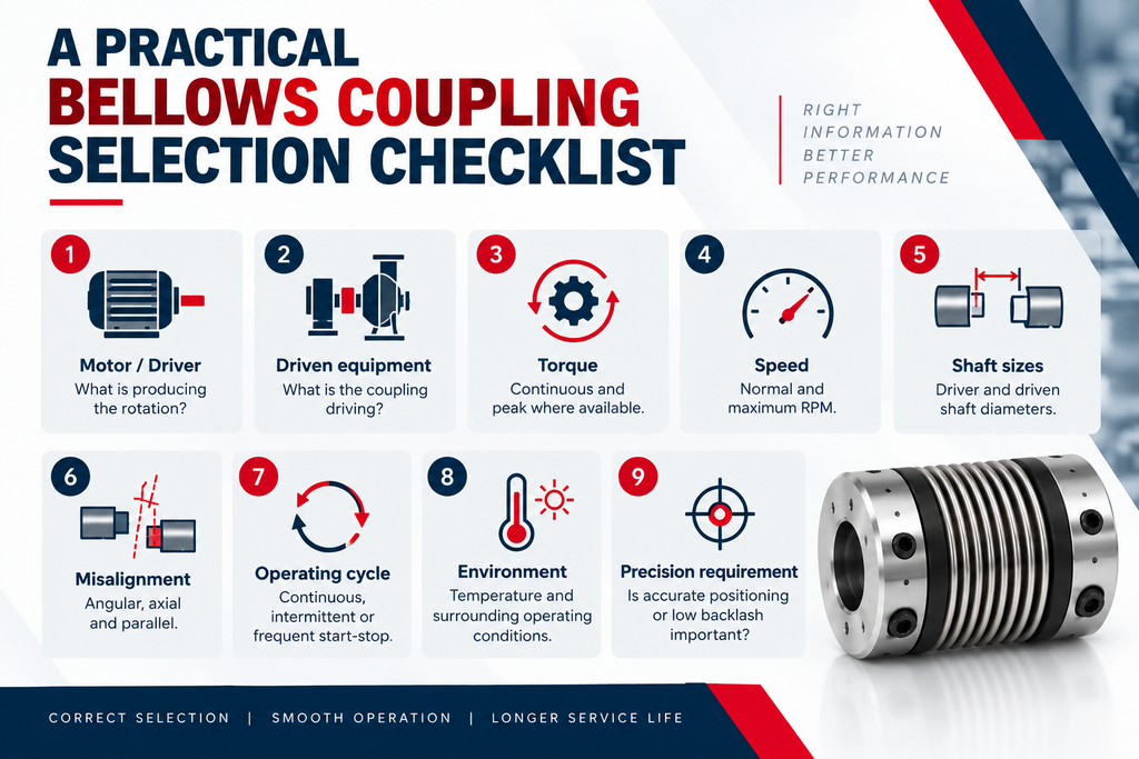
Before sending an enquiry or opening a coupling catalogue, collect the basic machine information:
Motor / Driver: What is producing the rotation?
Driven equipment: What is the coupling driving?
Torque: Continuous and peak where available.
Speed: Normal and maximum RPM.
Shaft sizes: Driver and driven shaft diameters.
Misalignment: Angular, axial and parallel.
Operating cycle: Continuous, intermittent or frequent start-stop.
Environment: Temperature and surrounding operating conditions.
Precision requirement: Is accurate positioning or low backlash important?
Providing this information makes coupling selection considerably more useful than asking only for a particular outside diameter.
Frequently Asked Questions About Bellows Couplings
What is a bellow coupling?
A bellows coupling is a flexible shaft coupling that uses a corrugated metallic bellows section to transmit torque while accommodating limited shaft misalignment.
What is a bellows coupling used for?
Common bellow coupling uses include servo systems, encoders, CNC machinery, robotics, automation and precision positioning equipment.
What are the main bellows coupling advantages?
Important advantages can include high torsional stiffness, low or zero backlash, compact construction and the ability to accommodate specified shaft misalignment.
What are the disadvantages of bellows couplings?
Potential disadvantages include limited misalignment capacity, sensitivity to incorrect installation and suitability for a narrower range of shock-loading conditions compared with some elastomeric coupling designs.
What causes bellows coupling failure?
Common contributors include excessive misalignment, overload, incorrect sizing, installation damage, abnormal vibration and operating beyond the coupling’s specified limits.
How do I choose a bellows coupling size?
Start with required torque, maximum RPM, shaft diameters, misalignment, torsional stiffness and mounting requirements. Then compare these values with the manufacturer’s size chart or technical catalogue.
Is a bellows coupling the same as a flexible coupling?
A bellows coupling is a type of flexible coupling, but not every flexible coupling uses a metallic bellows. Jaw, disc, pin bush and elastomeric designs use different methods to provide flexibility.
Final Selection Should Start With the Machine, Not the Catalogue
Bellows couplings solve a fairly specific engineering problem: transmitting rotation accurately while allowing controlled flexibility between connected shafts.
That makes them valuable for servo motors, encoders, CNC equipment, robotics, automation and other precision systems.
But the advantages only matter when the coupling is correctly selected.
Torque, RPM, shaft diameter, allowable misalignment, torsional stiffness and operating conditions should all be checked before deciding on a size.


