
If you work anywhere near rotating machinery pumps, compressors, motors, gearboxes, conveyors you already know that a coupling is far more than a simple connector between two shafts. It’s the component that transmits torque, absorbs misalignment, dampens vibration, and often acts as the first line of defense when something goes mechanically wrong. Choose the right coupling, and your equipment runs smoothly for years with minimal downtime. Choose the wrong one, and you’ll be dealing with premature bearing failure, seal leaks, excessive vibration, or a costly unplanned shutdown.
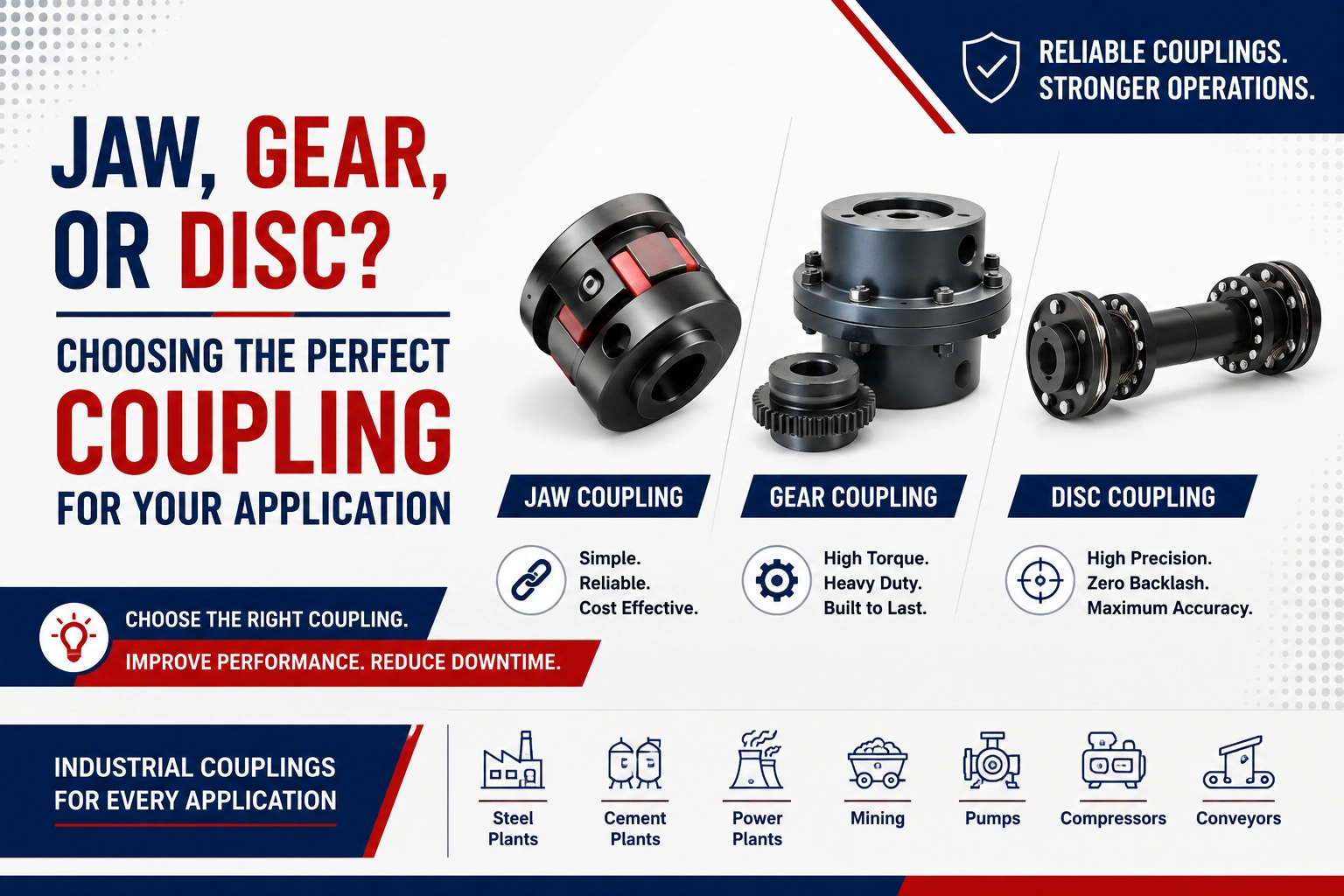
As a leading industrial coupling distributor, we’re often asked which coupling design is the right fit for a given drivetrain. Among the dozens of coupling types on the market, three stand out as the workhorses of industrial power transmission: jaw couplings, gear couplings, and disc couplings. Each has a distinct design philosophy, a specific sweet spot of applications, and a set of trade-offs that make it the “right” choice in one scenario and the wrong choice in another. This guide breaks down how each one works, where it shines, where it falls short, and how to actually decide which one belongs in your system.
Why Coupling Selection Matters More Than It Seems
Before comparing the three types, it’s worth understanding what a coupling actually has to do on a DRIVE SHAFT. In a perfect world, two shafts would line up exactly same centerline, same angle, no gap variation and a rigid coupling would suffice. In the real world, shafts are never perfectly aligned. Thermal growth, foundation settling, manufacturing tolerances, and assembly error all introduce three kinds of misalignment:
- Parallel (offset) misalignment — the shaft centerlines are parallel but not collinear.
- Angular misalignment — the shaft centerlines intersect at an angle rather than running parallel.
- Axial (end) float — the shafts move toward or away from each other along their length, often due to thermal expansion.
A flexible coupling’s job is to accommodate some combination of these movements while still transmitting torque efficiently, without imposing excessive reactionary loads on the connected bearings. How a coupling accomplishes this through an elastomeric element, meshing gear teeth, or flexing metal discs defines its performance envelope, maintenance needs, and cost.
Jaw Couplings: The Simple, Economical Workhorse
How They Work
A jaw coupling consists of two metal hubs, each with jaw-like projections, connected through a resilient insert (commonly called a “spider”) made of an elastomer such as urethane, Buna-N, Hytrel, or bronze in specialty cases. The spider sits between the interlocking jaws of the two hubs. When torque is applied, the jaws compress the spider’s legs, and it’s this compression not shear that transmits the load in most designs (this is often marketed as the “Lovejoy” style, named after the company that popularized it).
Strengths
- Simplicity and low cost. Jaw couplings have very few parts, are easy to install, and are among the least expensive flexible couplings on the market.
- No lubrication required. Because there’s no metal-to-metal sliding contact, jaw couplings are maintenance-friendly and won’t leak grease or oil onto surrounding equipment.
- Vibration dampening. The elastomer spider absorbs shock loads and vibration far better than a rigid metal coupling, which is valuable for reciprocating equipment or systems with frequent start-stop cycles.
- Easy field replacement. Many jaw coupling designs allow the spider to be swapped out without moving the connected equipment (a “sandwich” or open-spider design), which is a huge advantage for maintenance downtime.
- Electrical isolation. The elastomeric spider breaks electrical continuity between shafts, which can help prevent stray current damage to bearings in motor-driven systems.
Limitations
- Lower torque capacity. Jaw couplings generally handle less torque per unit size than gear or disc couplings, so at high horsepower they can become bulky.
- Limited misalignment capacity. They tolerate modest angular and parallel misalignment but far less than gear couplings, and essentially no significant axial float beyond what the spider can compress.
- Spider wear and degradation. The elastomer element wears out over time, especially in high-temperature environments, exposure to oils/chemicals, or under heavy cyclic loading. It needs periodic inspection and replacement.
- Backlash after wear. As the spider compresses and wears unevenly, some backlash (a rotational dead zone) can develop, which is undesirable in precision motion applications.
Best Applications
Jaw couplings are ideal for small to mid-size pumps, fans, blowers, mixers, general motor-to-gearbox connections, and light-to-moderate industrial applications where cost, simplicity, and vibration damping matter more than ultra-high torque or precision. They’re a go-to choice in HVAC systems, water treatment plants, packaging machinery, and general-purpose OEM equipment.
Gear Couplings: The High-Torque, High-Misalignment Specialist
How They Work
A gear coupling uses two hubs with external gear teeth that mesh with internal teeth cut into a surrounding sleeve or cover. The teeth are typically crowned (curved along their width) rather than straight-cut, which allows the mesh to accommodate angular misalignment while still transmitting torque through direct gear-tooth contact. Most gear couplings require lubrication (grease or oil) to reduce friction and wear between the meshing teeth, and they’re sealed to retain that lubricant.
Strengths
- Very high torque density. Gear couplings can transmit enormous torque relative to their size, making them a preferred choice in heavy industrial and high-horsepower applications like steel mills, marine propulsion, and large compressors.
- Excellent misalignment tolerance. The crowned-tooth design allows gear couplings to handle more angular misalignment than jaw or disc couplings, and double-engagement (two gear meshes with a spacer between them) designs can also accommodate significant parallel offset.
- Durability under heavy, continuous loads. Properly lubricated gear couplings hold up extremely well in demanding, continuous-duty, high-horsepower service.
- Compact for the torque they carry. For a given torque rating, gear couplings tend to be more compact than jaw couplings.
Limitations
- Lubrication maintenance. This is the single biggest drawback. Gear couplings need regular relubrication (or continuous lubrication in some designs), and seal failure leading to lubricant loss is one of the most common failure modes in the field. Neglected lubrication accelerates tooth wear dramatically.
- Higher cost and complexity. More precision machining (crowned gear teeth, sealed covers) makes gear couplings pricier than jaw couplings.
- Windup and backlash under reversing loads. Because torque is transmitted through meshing teeth with some clearance, gear couplings can develop backlash over time, which is a concern in applications with frequent reversing or precise positioning needs.
- Less vibration damping. Being an all-metal, rigid-tooth design, gear couplings transmit vibration and shock more readily than elastomeric jaw couplings.
- Environmental and disposal concerns. Grease-lubricated designs can throw off lubricant during operation, which is a housekeeping and environmental consideration in clean or food-grade environments.
Best Applications
Gear couplings dominate in heavy industry: steel and metal processing mills, large pumps and compressors, marine propulsion shafting, cement and mining equipment, and other high-torque, continuous-duty drivetrains where torque density and misalignment capacity outweigh maintenance burden.
Disc Couplings: The Precision, Maintenance-Free Performer
How They Work
A disc coupling transmits torque through a stack of thin, flexible metal discs (or a single contoured diaphragm in diaphragm-style couplings) bolted alternately to the driving and driven hubs. Torque is carried in shear/tension through the disc pack, while the discs flex to accommodate misalignment. There are no gear teeth, no elastomers, and critically no lubrication required, since there’s no sliding or rolling contact between components.
Strengths
- Zero backlash. Because torque transmission occurs through the disc pack’s flexing rather than any mechanical clearance, disc couplings are essentially backlash-free, making them the top choice for precision and positioning-sensitive applications.
- No lubrication, low maintenance. With no wear surfaces requiring grease or oil, disc couplings are extremely low-maintenance and well-suited to environments where lubricant leakage would be unacceptable (clean rooms, food and pharmaceutical processing, laboratory equipment).
- High-speed capability. Because they’re lightweight, well-balanced, and lack the mass distribution issues of gear couplings, disc couplings often perform exceptionally well at high rotational speeds.
- Excellent for combined misalignment. Disc couplings handle angular, parallel, and axial misalignment well, though generally less parallel offset capacity than gear couplings without added spacer length.
- Long service life with proper installation. When installed within specified misalignment limits, the discs undergo very low stress cycles and can last for many years without degradation.
Limitations
- Sensitive to installation misalignment. Disc couplings have a defined misalignment limit, and exceeding it even briefly can fatigue and crack the discs, sometimes leading to sudden failure rather than gradual wear. Precise alignment during installation is more critical here than with jaw or gear couplings.
- Higher upfront cost. Precision-manufactured metal discs and hubs typically cost more than an equivalent jaw coupling.
- No vibration damping. Like gear couplings, the all-metal construction means little to no shock absorption vibration and torsional shock pass through more directly.
- Torque capacity per size can be lower than gear couplings at the very high end, though modern multi-disc-pack designs have closed much of that gap.
Best Applications
Disc couplings are the standard in applications demanding precision, high speed, and low maintenance: turbines, compressors, precision pumps, machine tools, test stands, and any drivetrain where backlash-free operation and lubrication-free service life are priorities. They’re also common in retrofit situations replacing gear couplings specifically to eliminate relubrication maintenance.
Head-to-Head Comparison
| Criteria | Jaw Coupling | Gear Coupling | Disc Coupling |
|---|---|---|---|
| Torque capacity | Low–Moderate | Very High | Moderate–High |
| Misalignment tolerance | Low–Moderate | High | Moderate–High |
| Backlash | Some (as spider wears) | Some (tooth clearance) | None |
| Lubrication needed | No | Yes | No |
| Vibration/shock damping | Excellent | Poor | Poor |
| Maintenance burden | Low | High | Low |
| High-speed suitability | Moderate | Moderate | Excellent |
| Typical cost | Lowest | Highest | Moderate–High |
| Common industries | General industrial, HVAC, pumps | Steel, marine, heavy mining | Precision machinery, turbines, clean environments |
So, Which One Is “Best”?
There’s no universal winner the right coupling is entirely a function of your application’s priorities. That said, here’s a practical way to decide:
Choose a jaw coupling if: you need a cost-effective, low-maintenance solution for moderate torque and speed, your system experiences vibration or shock loading that benefits from elastomeric damping, and you want a component that’s dead simple to install, inspect, and replace without special tools.
Choose a gear coupling if: your application demands very high torque in a compact envelope think heavy industrial drivetrains and you can commit to a proper lubrication maintenance schedule. If misalignment is significant and torque is the dominant design constraint, gear couplings are hard to beat, provided you’re not in an environment where periodic relubrication is impractical.
Choose a disc coupling if: precision matters no backlash, high-speed balance, and long-term reliability without a lubrication schedule. This is the natural choice for turbines, precision pumps, machine tools, and any facility (like food/pharma processing) where lubricant contamination is a non-starter.
Getting this decision right up front pays dividends in reduced downtime, lower total cost of ownership, and fewer surprise failures which, in industrial rotating equipment, is often the difference between a smoothly running plant and an expensive unplanned outage.
At SGF Coupling, our team can help you match the right coupling design to your specific torque, misalignment, speed, and maintenance requirements.


